- 您现在的位置:买卖IC网 > Sheet目录180 > 2866239 (Phoenix Contact)UPS 24VDC 20A DIN RAIL
�� ���
���
���Uninterruptible� Power� Supply� Unit� for� Universal� Use� –� QUINT-DC-UPS/24DC/20�
�3.� Device� View,� Connections,� and� Control� Elements�
�7�
�8�
�3� 14� D�
�O� K� C� +�
�13�
�14� O� D� C�
�K� +�
�+� +�
�9�
�+2�
�13�
�3� 14� D�
�0,2�
�11� 14� O� D� C�
�21� OK� C� +�
�1� R1� +�
�R2�
�m� R2�
�33�
�m�
�ote�
�21�
�Ba�
�OF�
�ON� F�
�Mo� t.-�
�Ch� t.-�
�ge�
�Ba� at.-M�
�ha� de�
�e�
�we�
�OK�
�[m� ax� 0,5� 1�
�in]� ∞�
�D� Ba�
�In� C� 24�
�t.-S�
�ele�
�pu�
�[A� t�
�V�
�+�
�t�
�h]�
�20�
�–�
�A�
�O�
�≤� 3,�
�u�
�≥� 12� 2�
�+� tput�
�–�
�Ba�
�+� ter�
�Ala�
�Mo� rge�
�Ba� -Ch�
�OK�
�Ba�
�we�
�/22� C�
�/20� A�
�/24� 9�
�DC� VD�
�C-U� 6� 2.5� DC/2�
�T-D� o.:� 2�
�ge� 24V�
�UIN� r-N� o� lta�
�Ord� ut:� ona�
�70� F�
�Inp� erati� +� ??� 58� °�
�Op� tput:�
�5…� +1�
�-2� …�
�Ou� 3�
�-1�
�–2�
�F�
�TR�
�S�
�AL� DUS� ROL� NT�
�OV�
�PR�
�AP�
�EQ� KA�
�U�
�TE�
�at�
�st� a� ll� ting�
�in� nec�
�a� d� con�
�R� e� re�
�be�
�00�
�EN� 500�
�ns�
�ct�
�st�
�4�
�5�
�6�
�1�
�4V�
�A�
�11� 23� R1�
�13�
�r�
�K�
�31� +� +�
�2� –�
�2� 2�
�Ala� 32� Re�
�31�
�de� Ba�
�ar�
�Ala�
�rm�
�B�
�t.-C� o�
�rg�
�Po�
�r� In�
�t�
�m�
�30�
�20�
�c�
�t�
�2�
�3�
�5�
�15� 10�
�Ser�
�vice�
�4�
�7,�
�y�
�–�
�Po�
�rm�
�de�
�t.-� a�
�t.�
�r� In�
�LIS�
�D�
�DC�
�PS� 6� 23� 24V� -30� 0A�
�:� 2�
�5�
�L�
�IA�
�IN� NT� ME�
�CO� UIP�
�43�
�fo�
�Q� e� lV� °� C�
�io�
�n�
�in�
�0-6�
�61� 81-1�
�EN�
�io�
�ru�
�§�
�-2�
�"�
�!�
�0�
�2�
�3�
�$�
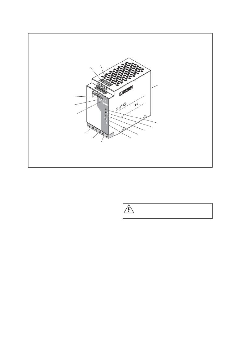
�Figure� 04�
�1� DC� input:� 24� V� unbuffered�
�Input� voltage� 24� V� DC�
�(0.5� mm� 2� to� 16� mm� 2� solid)�
�(0.5� mm� 2� to� 10� mm� 2� stranded)�
�(20� -� 6� AWG)�
�Internal� fuse� 25� AT�
�2� DC� output:� 24� V� buffered�
�Output� voltage� 24� V� DC�
�(0.5� mm� 2� to� 16� mm� 2� solid)�
�(0.5� mm� 2� to� 10� mm� 2� stranded)� (20� -� 6� AWG)�
�The� device� is� idling-proof� and� short-circuit-proof.�
�3� 24� V� battery� module� connection�
�4� Floating� PDT� (11,12,13):� Alarm�
�5� Floating� PDT� (21,22,23):� Battery� Mode�
�6� Floating� PDT� (31,32,33)�
�7� 24� V� supply� voltage,�
�maximum� current� limit� 0.2� A� for� grouped� contacts�
�11,� 21,� 31�
�8� Remote� shutdown� (R1,� R2)�
�9� Universal� DIN� rail� adapter� UTA� 107�
�0� Red� LED:� Alarm�
�!� Yellow� LED:� Battery� Mode/Battery� Charge�
�"� Green� LED:� Power� In� OK�
�§� Buffer� time� setting� 0.5� -� 30� minutes�
�$� Battery� module/Service� setting� selection�
�4.� Safety� Notes� and� Warning�
�Instructions�
�To� ensure� that� the� device� can� be� operated� safely�
�and� all� functions� can� be� used,� please� read� these�
�instructions� carefully.�
�Caution:� Never� carry� out� work� when� the�
�power� is� turned� on,� this� is� highly�
�dangerous.�
�The� QUINT-DC-UPS� is� a� built-in� device.� Installation�
�and� startup� must� only� be� carried� out� by� quali� ?� ed�
�personnel.� The� relevant� country-speci� ?� c� regulations�
�(e.g.,� VDE,� DIN)� must� also� be� observed.�
�Before� startup� it� is� particularly� important� to� ensure�
�that:�
�?� All� supply� lines� have� suf� ?� cient� fuse� protection� and�
�are� the� correct� size.�
�?� All� output� cables� are� the� correct� size� for� the� maximum�
�device� output� current� or� have� separate� fuse�
�protection.�
�?� Suf� ?� cient� convection� is� ensured.�
�PHOENIX� CONTACT� page� 4� of� 9�
�发布紧急采购,3分钟左右您将得到回复。
相关PDF资料
2866242
UPS 24VDC 40A DIN RAIL
2866255
PWR SUPPLY 5A 100-240AC 48VDC
2866297
PWR SUPPLY 8A 100-240AC 10-15VDC
2866336
PWR SUPPLY 100W 100-240AC 24VDC
2866446
POWER SUPPLY 1.3A 100-240AC 24DC
2866640
UPS 24VDC 2A
2866653
POWER SUPPLY 1.5A 24VDC
2866679
POWER SUPPLY 5A 85-264AC 48DC
相关代理商/技术参数
2866242
功能描述:UPS - 不间断电源 QUINT-DC-UPS/24DC/40
RoHS:否 制造商:Phoenix Contact 功率额定值: 输出电压额定值:24 V 出口数量:2 运行时间(满载): 运行时间(半载):
28-6625-10
功能描述:IC 与器件插座 DIP HEADERS 28 PINS SCREW MACHINE CONT RoHS:否 制造商:Molex 产品:LGA Sockets 节距:1.02 mm 排数: 位置/触点数量:2011 触点电镀:Gold 安装风格:SMD/SMT 端接类型:Solder 插座/封装类型:LGA 2011 工作温度范围:- 40 C to + 100 C
28-6625-11
功能描述:IC 与器件插座 DIP HEADERS 28 PINS SCREW MACHINE CONT RoHS:否 制造商:Molex 产品:LGA Sockets 节距:1.02 mm 排数: 位置/触点数量:2011 触点电镀:Gold 安装风格:SMD/SMT 端接类型:Solder 插座/封装类型:LGA 2011 工作温度范围:- 40 C to + 100 C
28-6625-20
功能描述:IC 与器件插座 DIP HEADERS 28 PINS SCREW MACHINE CONT RoHS:否 制造商:Molex 产品:LGA Sockets 节距:1.02 mm 排数: 位置/触点数量:2011 触点电镀:Gold 安装风格:SMD/SMT 端接类型:Solder 插座/封装类型:LGA 2011 工作温度范围:- 40 C to + 100 C
28-6625-21
功能描述:IC 与器件插座 DIP HDR 28P GLD RoHS:否 制造商:Molex 产品:LGA Sockets 节距:1.02 mm 排数: 位置/触点数量:2011 触点电镀:Gold 安装风格:SMD/SMT 端接类型:Solder 插座/封装类型:LGA 2011 工作温度范围:- 40 C to + 100 C
28-6625-31
功能描述:IC 与器件插座 DIP HEADERS 28 PINS SCREW MACHINE CONT RoHS:否 制造商:Molex 产品:LGA Sockets 节距:1.02 mm 排数: 位置/触点数量:2011 触点电镀:Gold 安装风格:SMD/SMT 端接类型:Solder 插座/封装类型:LGA 2011 工作温度范围:- 40 C to + 100 C